| flash | ||
| images | ||
| openwrt/target/linux/ath79 | ||
| Readme.md | ||
Porting OpenWRT to a board with a supported SoC
Intro
Recently, some network devices caught my attention both on Aliexpress and Alibaba. Specifically, I found some interesting outdoor equipment for a very low price, ranging between 10-25$.
https://it.aliexpress.com/item/32964460654.html https://it.aliexpress.com/item/4000091742124.html https://www.alibaba.com/product-detail/AR9331-long-range-wifi-192-168_62106638650.html
These are 2.4ghz AR9330 based boards, powered via POE (although on a non standard voltage), with two 10/100/1000 ethernet ports, an integrated antenna and a waterproof enclosure. I received the first one from Aliexpress but i plan to get some other to test as well.
There's a video on YouTube of someone unpacking and reviewing it. It also show the OEM web interface.
Pictures
PCB
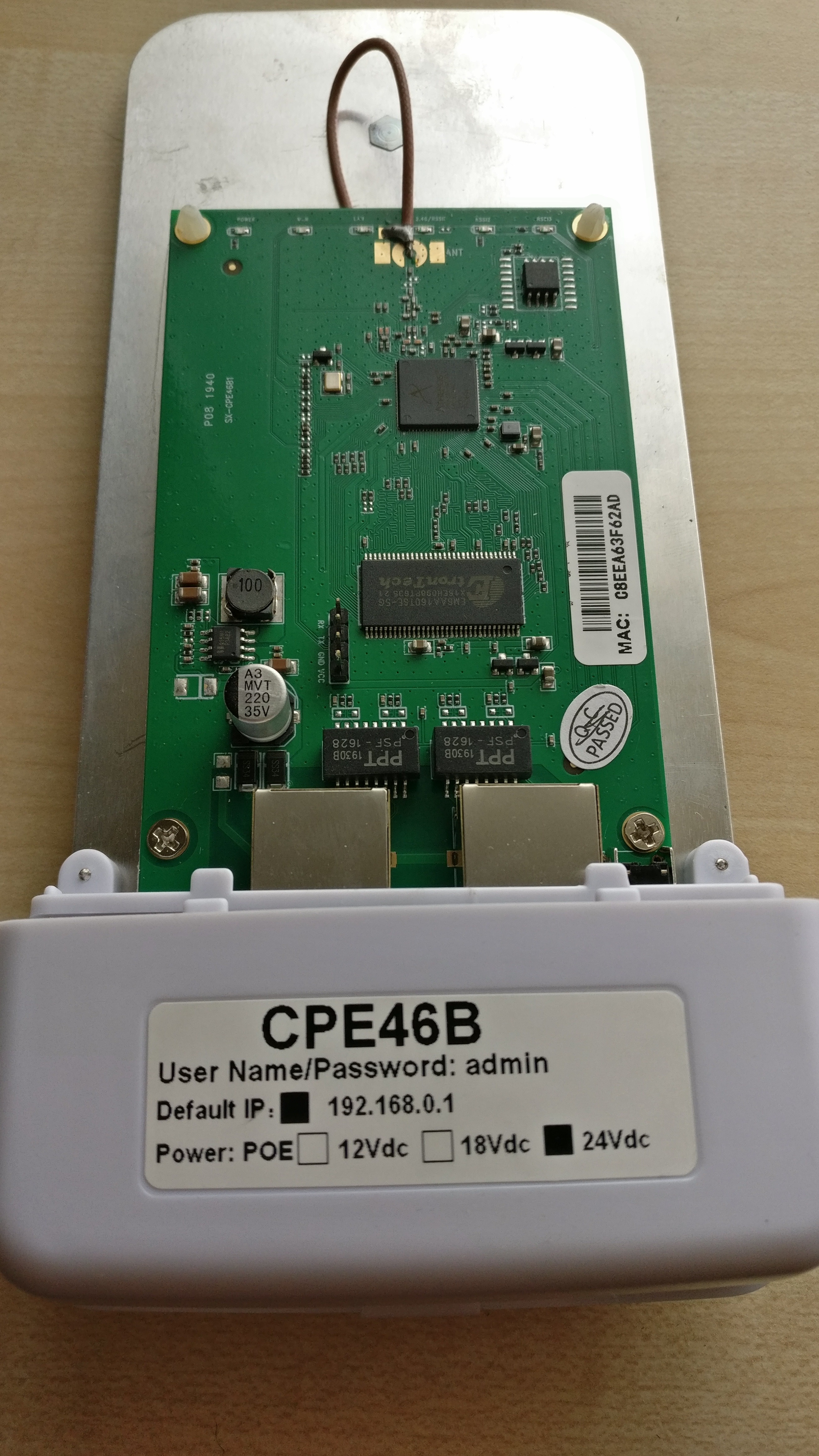
From the PCB picture it is clear that the board has an easily accessible serial header and that it has a SOIC8 flash chip (Winbond 25Q64). Given this info, there are two possibilities to start learning about the board via hardware: connecting to the serial console and get whatever the oem firmware prints out and do a direct hardware image of the flash chip.
Dumping the original firmware without hardware
Before even trying the SOIC clip or the serial port i wanted to check around the stock firmware. It looks like the device has no DHCP server but it has a fixed 192.168.0.1 ip address and default admin:admin credentials.
By default, there's only the web intrace and a telnet server listening on the public interface. The credentials for the telnet interface are root without password.
 CPE46B mips #1 Thu Sep 5 18:02:48 CST 2019 (none)
CPE46B login: root
Ziking logintalk start ...................


Interactive mode

> ?
Unknown command '?'
 help                          :Show this usage help
 art.sh                        :Run art server
 get_log                       :Download log from ap to remote.  Usage: get_log [remote ip]
 ifconfig                      :Network configuration commands
 ip                            :Network configuration commands
 iwconfig                      :Wlan configuration commands
 iwpriv                        :Wlan configuration commands
 iwlist                        :Wlan configuration commands
 oem                           :Change/Show MAC address & sn; Usage: oem get/set
 ping                          :Command ping
 ps                            :Command ps
 route                         :Network configuration commands
 sendAT                        :Send AT command for lte device
 show_oem                      :Show OEM infomation
 show_ver                      :Show AP software version
 tc                            :Qos configuration commands
 top                           :Command top
 wlanconfig                    :Athreos wlan configuration commands
 T1                            :Test 5G RF with 20M bandwidth
 T2                            :Test 5G RF with 40M bandwidth
 T3                            :Test 2.4G RF with 20M bandwidth
 T4                            :Test 2.4G RF with 40M bandwidth
 T5                            :Test upload.Usage: T5 [remote ip]
 T6                            :Test download.Usage: T6
>
While upon collecting the user is dropped in a restriced pompt with few commands available, it is possible to inject commands in almost any of it via common shell separators |;&.
With the command injection is easy to understand that the device is already running a heavily customized OpenWRT fork, running on Linux 2.6.31.
> iwconfig|uname -a
lo        no wireless extensions.

eth0      no wireless extensions.

eth1      no wireless extensions.

wifi0     no wireless extensions.

br0       no wireless extensions.

Linux CPE46B 2.6.31--LSDK-9.2.0_U9.915 #1 Thu Sep 5 18:02:48 CST 2019 mips GNU/Linux
Catting /proc/mtd gives more info about flash layout.
> iwconfig|cat /proc/mtd
dev:    size   erasesize  name
mtd0: 00010000 00010000 "u-boot"
mtd1: 00010000 00010000 "u-boot-env"
mtd2: 00360000 00010000 "rootfs"
mtd3: 00100000 00010000 "uImage"
mtd4: 00360000 00010000 "rootfs1"
mtd5: 00010000 00010000 "NVRAM"
mtd6: 00010000 00010000 "ART"
By knowing the size of each mtd partition, we get to know that it has a 8M flash chip. This makes sense given that the chip has written on it 25Q64, where 64 is the size in Megabits.
Using dd it is possible to dump each partition, download it and even reasseble the full firmware image simply with cat afterwards.
for X in 0..5
> iwconfig|dd if=/dev/mtd0 of=/var/tmp/web/mtdX
for X in 0..5
# wget http://192.168.0.0.1/mtdX
# cat mtd0 mtd1 mtd2 mtd3 mtd4 mtd5 mtd6 > flash.bin
# ls -lart flash.bin
-rwxrwxrwx 1 user user 8388608 Apr 12 12:40 flash.bin
Where 8388608/1024=8192K.
When the device boots up, a lot of custom scripts and services will run. The most custom part of the firmware, which means the web interface and their custom binaries are somehow encrypted or more simply obfuscated and loaded at runtime in ram. At rest, the obfuscated files are called /usr/web.bin, /usr/sbin.bin, /usr/apps.bin. The executable responsabile for decrypting them to more simpler tgz archives is called ap_monitor. Ghidra sucessfully decompile this binary and the obfuscation mechanism is not very complicated and could reversed with not too much effort but there's proably no reason to do so.
The
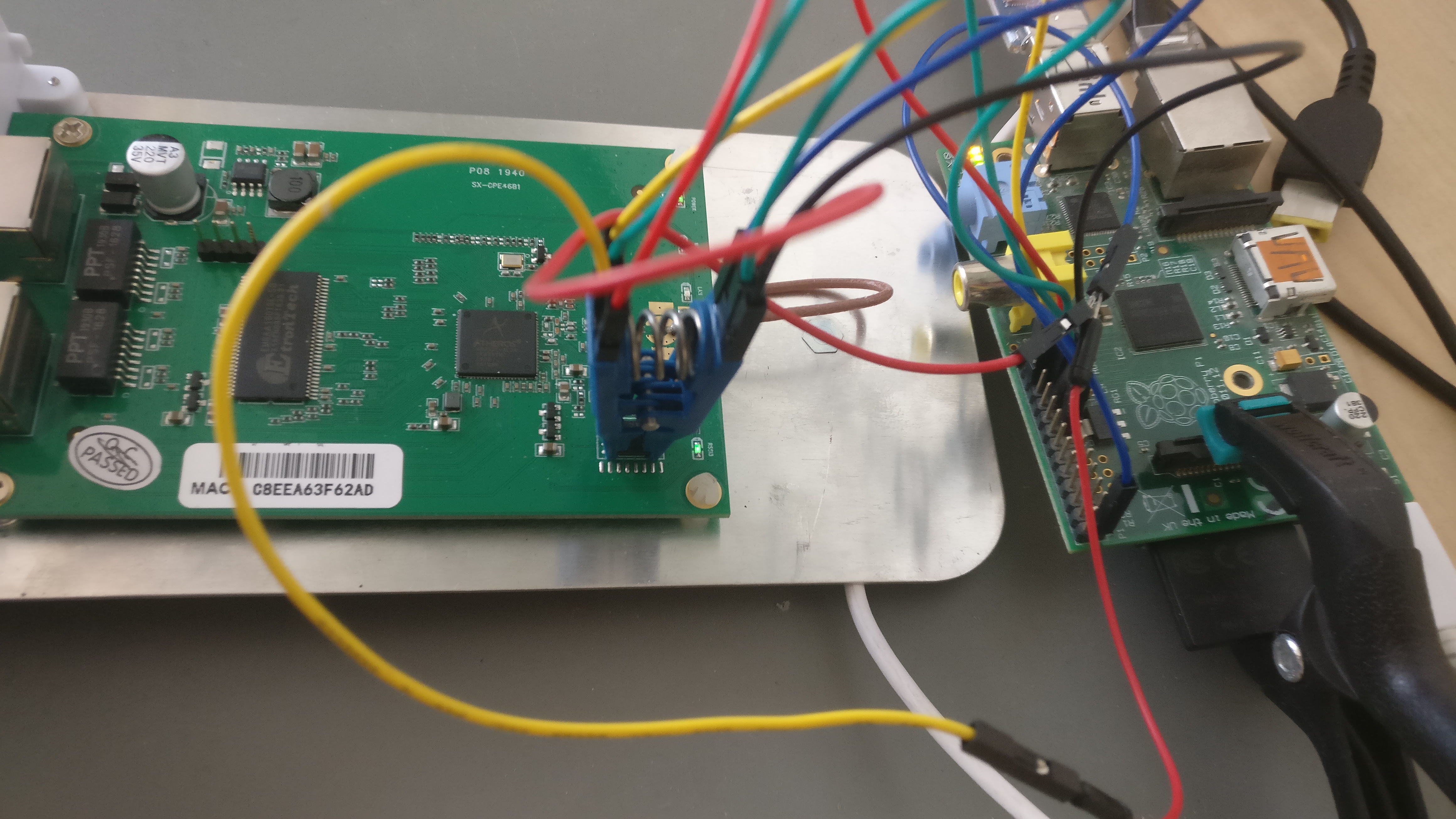
Raspberry PI GPIO with a SOIC8 CLIP
The following istruction are recycled from this other guide.
    ______
1--| O    |--8
2--|      |--7
3--|      |--6
4--|______|--5
Remeber to research your chip model and manufacturer and double check the pin layout using the official datasheet.
| 1 | 2 | 3 | 4 | 5 | 6 | 7 | 8 | Flash pin number |
|---|---|---|---|---|---|---|---|---|
| CS | DO | /WP | GND | DI | CLK | /HOLD | VCC | Pin name |
| 24 | 21 | GND | 25 | 19 | 23 | GND | 17 | Rpi GPIO number |
Please refer to the multiple flashing guides available
- https://www.flashrom.org/RaspberryPi
- https://libreboot.org/docs/install/rpi_setup.html
- https://karlcordes.com/coreboot-x220/
- https://tylercipriani.com/blog/2016/11/13/coreboot-on-the-thinkpad-x220-with-a-raspberry-pi/
- https://github.com/bibanon/Coreboot-ThinkPads/wiki/Hardware-Flashing-with-Raspberry-Pi
From a root prompt on the Rpi
# flashrom -p linux_spi:dev=/dev/spidev0.0,spispeed=1000 -r flash1.bin
# flashrom -p linux_spi:dev=/dev/spidev0.0,spispeed=1000 -r flash2.bin
# flashrom -p linux_spi:dev=/dev/spidev0.0,spispeed=1000 -r flash3.bin
# sha1sum flash*.bin
Check that all the checksums do match. In case they don't there's probably something wrong in the clip position or in the wiring. Remember that no pin should left floating even if it's not useful for the operation. /WP and /HOLD should be always connected to something like GND or VCC.
Serial interface
The serial header is easy to work with and has clearly written the pinout on it. Any cheap usb adapter will probably work. In my case the baudrate is 115200, however, a script like baudare.py should do the trick.
Common softwares for serial communication are minicom and screen.
# screen /dev/ttyUSB0 115200


